APEX EcoBuilt
Leading Manufacturer of Aluminum Systems & Modular Housing
APEX EcoBuilt
Leading Manufacturer of Aluminum Systems & Modular Housing
 21 May, 2026Knowledges
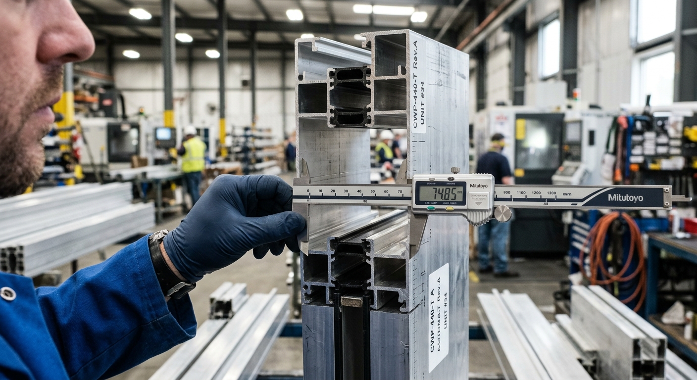
Before signing off on a curtain wall package, developers need to verify five specific things in the wind load calculation: the design pressures (positive and negative) for every facade zone, the code and wind speed used as the basis, how corner and parapet zones are treated, the deflection limits the system meets at design load, and the mock-up test pressures it has actually passed. Get those five right and you eliminate roughly 90% of the wind-driven facade failures we see on projects globally. Miss any one of them and you may be approving a system that looks fine on paper but will leak, rattle, or worse on the first serious storm.
The single fastest way to spot a weak wind load report? Check what code it cites before you look at any numbers. If the calculation doesn’t open with a specific reference standard, project wind speed, exposure category, and building risk category, the rest of the document isn’t trustworthy.
For a project in Dubai, you’d expect to see Dubai Municipality circulars referencing ASCE 7 or EN 1991-1-4, a basic wind speed around 45 m/s (3-second gust), and Exposure C for most urban sites. For a coastal Chinese project, GB 50009-2012 with a 50-year return basic wind pressure (often 0.55–0.85 kN/m² for Tier-1 coastal cities) is standard. A report that just says “designed per local code” with no equation, no map reference, no exposure call — push back immediately.

Here’s the counterintuitive bit: on most curtain wall failures, it’s not the wind pushing in that breaks the system — it’s the wind sucking out. Negative (suction) pressures at building corners and roof edges routinely run 2 to 2.5 times the positive pressure on the windward face.
For a 60-meter tower in Exposure C with a 45 m/s basic wind speed, you might see a windward design pressure of around +1.6 kPa on a mid-field panel. The corner zone on the same building? You can easily hit −3.5 to −4.0 kPa. If your supplier is sizing mullions and anchors only off the positive number, the corner units will pull out of their brackets in a strong squall.
Every zone — interior wall, edge zone, corner zone, parapet — must list paired positive AND negative pressures. A clean report tabulates them by elevation height bands (0–10 m, 10–20 m, etc.) because pressure increases with height. If the report has one pressure value for the “whole building,” that’s not engineering — that’s hand-waving.
Wind doesn’t hit a building uniformly. It accelerates around corners and lifts violently over parapets, which is why codes define narrow “edge zones” with sharply higher pressure coefficients. The width of these zones — called a in ASCE 7 — is typically the smaller of 10% of the least horizontal dimension or 0.4 times the mean roof height, but never less than 1 meter.
For a 40 m × 30 m tower at 80 m tall, that gives a corner strip about 3 m wide where pressures spike. A common contractor shortcut is to specify the same curtain wall unit type across the entire facade to simplify procurement. That’s fine — as long as the standard unit was engineered for the corner pressure, not the mid-field one.
“Show me the calculation for the worst-case corner unit at the highest elevation, including anchor pull-out capacity with a safety factor of 4 on adhesive anchors or 3 on mechanical anchors.” If they can’t produce that page in 24 hours, the calc isn’t done — it’s been promised.
A curtain wall can be strong enough not to break and still be defective. If the mullions deflect too much under design wind load, glass seals fail, gaskets pop out, and the facade leaks for the next twenty years. Industry standard for framing deflection is L/175 of the span or 19 mm, whichever is less — referenced in AAMA TIR-A11 and echoed in most national codes.
For laminated or insulating glass units, the glass center deflection must also be limited, typically to L/60 or 25 mm. Push your supplier to show calculations at the actual design pressure, not at some reduced “serviceability” pressure they invented to make the numbers work.
On a recent 22-story residential tower we supplied in Southeast Asia, the original third-party design called for 6063-T6 mullions at 1.5 m centers. Our engineering review showed deflection at the top floors hit L/160 under the verified design pressure — within the supplier’s claim but outside code. We upsized to a deeper mullion profile and the project signed off without rework on site. Catching that on paper cost a week; catching it after install would have cost months. That’s the kind of check our in-house engineering and manufacturing team runs on every order.
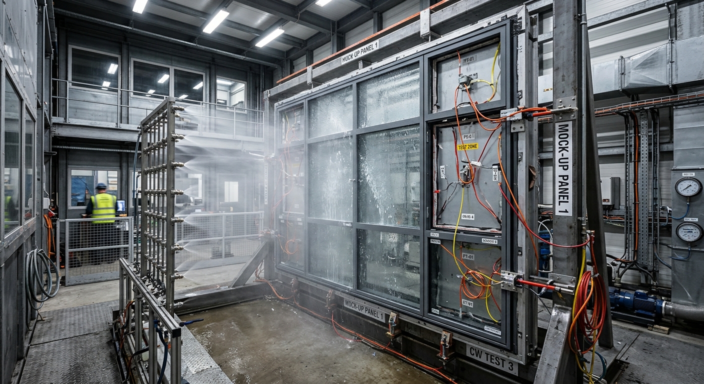
Calculations predict behavior. Mock-up tests prove it. For any curtain wall project over roughly 5,000 m² or any building taller than 30 m, you should require a Performance Mock-Up Test (PMU) to AAMA 501 or CWCT standards before mass production begins.
The pressures that matter on the test report:
For instance, a hotel developer we worked with on a Middle East coastal resort required the PMU to be witnessed by an independent engineer before any units shipped. Two minor gasket revisions came out of that test — caught in the lab, not on a 40-story tower. If you’re building in a high-wind or coastal environment, our notes on spec’ing curtain walls for Middle East climates covers the related thermal and sand-load considerations.
Most wind load reports show beautiful pressure diagrams and stop there. The honest question is: how does that pressure get from the glass into the building structure? Through the anchors. And anchor design is where corner-cutting happens most often.
For each anchor type — typically T-bolt slab edge anchors or cast-in channels — verify:
If the report shows a 12 mm anchor bolt at 75 mm embedment in 25 MPa concrete carrying 18 kN tension at 50 mm from a slab edge, that’s a red flag — the cone breakout capacity is probably below the demand. Make the supplier show the calc per ACI 318 Appendix D or EN 1992-4.
Wind pressure increases with height following a power law — the velocity pressure exposure coefficient Kz in ASCE 7 rises from about 0.85 at 10 m to 1.50 at 100 m in Exposure C. That’s nearly a 75% increase. So a curtain wall unit that’s safe on floor 5 may be undersized on floor 30.
Good suppliers handle this in one of two ways: zone the building vertically and use different mullion thicknesses or anchor patterns per zone, or engineer everything to the worst-case top-floor pressure (simpler, but heavier and more expensive). Both are fine. What’s not fine is using mid-height pressure as the design value and hoping the top floors hold.
Ask for a marked-up elevation showing pressure zones and which unit type goes where. If the elevation shows a single unit code across all 30 floors with no annotation, either the building is being over-engineered (you’re paying for steel you don’t need) or under-engineered at the top (you have a problem). Either way, you want to know which.
Code-based calculations work for regular building shapes up to about 150 m. Above that, or for unusual geometries — twisted towers, deep setbacks, clustered high-rises that create channeling — code methods get conservative or inaccurate, and you need a Wind Tunnel Study (WTS).
A proper WTS from a lab like RWDI, BMT, or CPP runs around USD 80,000–150,000 and takes 8–12 weeks. The output is a cladding pressure database with hundreds of tap locations and probabilistic pressure values at multiple return periods. Your curtain wall supplier should be receiving this directly from the wind consultant — not interpreting a summary memo.
For a recent landmark mixed-use development in Asia partnering with a major developer group, the wind tunnel showed corner suction 30% higher than ASCE 7 predicted due to channeling from an adjacent tower. Catching that pre-design saved a structural retrofit. See more on how we handle complex facade projects on our completed projects page.
Bring this to the next sign-off meeting. If the supplier can’t tick every box with a document reference, the package isn’t ready.
Wind load verification isn’t glamorous, but it’s the single most cost-effective due diligence step on any curtain wall project — a few hours of review saves years of leak repairs and liability. If you’d like our engineering team to review your facade wind load package or quote a system that comes with full calc documentation already prepared, get in touch with apexecobuilt or browse our aluminum curtain wall systems to see what’s typically included in our deliverables.


Arabic

English

Spanish
Fill out the form below and our team will get back to you within 24 hours with a tailored solution.
